logo
ホーム 製品ロジャースPCB板

High-Frequency 2-Layer RF PCB RO4730G3 Material ENIG Finish

認証
中国 Bicheng Electronics Technology Co., Ltd 認証
顧客の検討
ケビン、 板-感謝--を非常に受け取り、テストした。これらは私達が必要とした何を完全、丁度である。 rgds 金持ち

—— 豊富なRickett

ルース、 私はPCBを今日得、それらはちょうど完全である。 少し忍耐を、私の次の順序すぐに来ているとどまりなさい。 ハンブルクからの親切な点 オラフ

—— オラフKühnhold

こんにちはNatalie。 それはあなたの参照のために完全、私付けるある映像をだった。そして私は割り当てるために次のプロジェクト2つ送る。 ありがとうたくさん再度

—— セバスチャンToplisek

ケビン、 ありがとう、それらは完全になされ、よく働く。約束されるように、私の最も最近のプロジェクトのためのリンクはあなたが私のために製造したPCBsを使用して、ここにである: 見なす、 ダニエル

—— ダニエル フォード

オンラインです

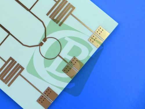
High-Frequency 2-Layer RF PCB RO4730G3 Material ENIG Finish

High-Frequency 2-Layer RF PCB RO4730G3 Material ENIG Finish

大画像 :  High-Frequency 2-Layer RF PCB RO4730G3 Material ENIG Finish

商品の詳細:
起源の場所: 中国
ブランド名: Bicheng
証明: UL, ISO9001, IATF16949
モデル番号: BIC-052.V1.0
お支払配送条件:
最小注文数量: 1pcs
価格: USD9.99-99.99
パッケージの詳細: 真空バッグ+カートン
受渡し時間: 8-9営業日
支払条件: T/T
供給の能力: 1か月あたり5000pcs

High-Frequency 2-Layer RF PCB RO4730G3 Material ENIG Finish

説明
基本材料: ロジャース RO4730G3 レイヤーカウント: 2層
PCBの厚さ: 0.6mm PCBサイズ: 59.6mm×40.5mm(
銅重量: 1オンス(1.4ミルまたは35μmに相当) 表面仕上げ: エレクトロレスニッケルイマージョンゴールド(enig)
ハイライト:

2-layer RF PCB RO4730G3

,

ENIG finish Rogers PCB

,

high-frequency Rogers PCB board

High-Frequency 2-Layer RF PCB RO4730G3 Material ENIG Finish

This is a high-quality, double-sided PCB engineered for radio frequency (RF) applications, particularly suited for antenna systems. It is fabricated using Rogers RO4730G3 antenna-grade laminate, ensuring superior electrical performance, reliability, and cost-effectiveness.


1. PCB Specifications

Specification Category Details
Base Material Rogers RO4730G3 (hydrocarbon/ceramic laminate) – Low-loss, high-frequency substrate; robust and economical alternative to traditional PTFE-based substrates.
Layer Count 2 layers
Physical Dimensions - Board size: 59.6mm x 40.5mm (1 piece)- Dimensional tolerance: ±0.15mm
Design Rules – Traces & Holes - Minimum Trace/Space: 5 mil / 5 mil- Minimum Drill Size: 0.4mm
Design Rules – Vias - Via Type: Through-hole vias only (no blind vias)- Via Plating Thickness: 20 μm
Board Thickness Finished board thickness: 0.6 mm
Copper Weight 1 oz (equivalent to 35 μm) on both outer layers
Surface Finish Electroless Nickel Immersion Gold (ENIG) – Provides a flat, solderable surface with excellent oxidation resistance; optimized for RF performance.
Solder Mask - Top side: Green (LPI, Liquid Photoimageable) solder mask- Bottom side: No solder mask (exposed copper)
Silkscreen - Top side: White legend silkscreen- Bottom side: No silkscreen


2. PCB Stack-up

Layer Position Material Thickness
Top Layer 35 μm Copper 35 μm (1oz)
Core Layer Rogers RO4730G3 0.508mm (20mil)
Bottom Layer 35 μm Copper 35 μm (1oz)


High-Frequency 2-Layer RF PCB RO4730G3 Material ENIG Finish 0


3. Key Material Features & Benefits (RO4730G3):

The use of Rogers RO4730G3 material provides significant advantages for RF designs:


-Optimized RF Performance: Stable dielectric constant (Dk) of 3.00 ± 0.05 at 10 GHz and an ultra-low dissipation factor of 0.0028 for reduced insertion loss.


-Low Passive Intermodulation (PIM): Ideal for cellular base station antennas where signal integrity is critical.


-Excellent Thermal Stability: High Tg >280°C and a low Thermal Coefficient of Dk (34 ppm/°C) ensure consistent electrical performance across temperature variations.


-Ease of Fabrication: Fully compatible with standard FR-4 multi-layer processing and lead-free assembly, eliminating the need for specialized PTFE treatments.


-Lightweight & Robust: Unique filler system makes the material 30% lighter than PTFE/glass and features a CTE matched to copper for enhanced reliability.


-Environmental Compliance: RoHS compliant and compatible with lead-free soldering processes.


Characteristic Category Technical Specification
Stable Dielectric Constant (Dk) 3.00 ± 0.05 at 10 GHz
Ultra-Low Signal Loss Dissipation factor of 0.0028 at 10 GHz
Superior Thermal Stability (TCDk) Thermal Coefficient of Dk: 34 ppm/°C
High Thermal Resilience - Glass Transition Temperature (Tg): >280°C- Decomposition Temperature (Td): 411°C (TGA)
Controlled Thermal Expansion (CTE) - X-axis: 15.9 ppm/°C- Y-axis: 14.4 ppm/°C- Z-axis: 35.2 ppm/°C
Efficient Heat Dissipation Thermal Conductivity: 0.45 W/mK


4. Typical Applications:

This PCB is ideally suited for:


-Cellular Base Station Antennas

-Various other RF and antenna applications requiring stable electrical performance and low loss.


Quality & Testing: Manufactured to IPC-Class-2 standards and undergoes 100% electrical testing prior to shipment to ensure functionality and reliability.


Artwork Format: Gerber RS-274-X– the universal industry standard, compatible with fabrication facilities worldwide.


Availability: This PCB is available for order and shipment worldwide.


High-Frequency 2-Layer RF PCB RO4730G3 Material ENIG Finish 1

連絡先の詳細
Bicheng Electronics Technology Co., Ltd

コンタクトパーソン: Ms. Ivy Deng

電話番号: 86-755-27374946

ファックス: 86-755-27374848

私達に直接お問い合わせを送信 (0 / 3000)